Future flow rate adjustability with Hydro-Brake Optimum
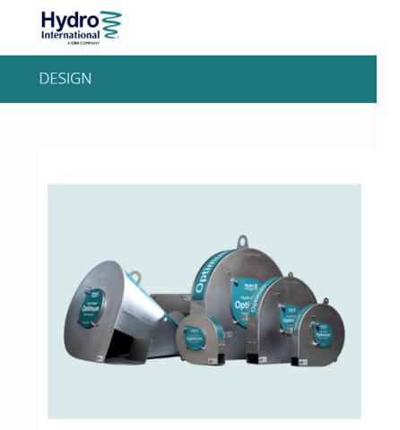
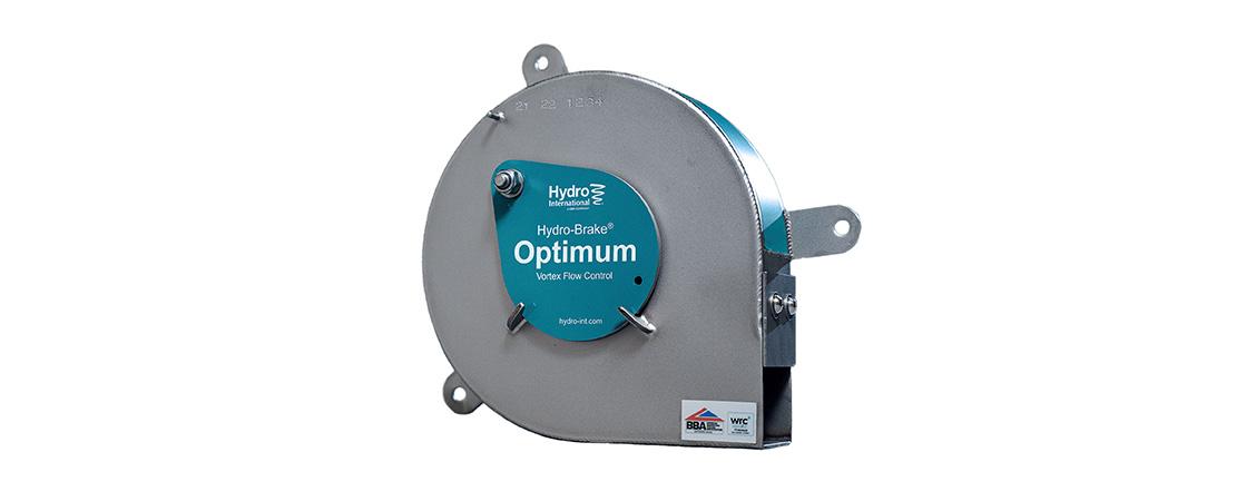
Our most popular and highest performing flow control, the hydraulic efficient Hydro-Brake® Optimum vortex flow control now incorporates future flow rate adjustability built in.
The adjustable inlet will enable engineers to future-proof their drainage design with up to plus or minus 20% change in design flow should additional developments or urban creep cause an increase in flows, saving the cost of a replacement flow control.
Our Hydro-Brake® Optimum vortex flow controls can be designed to meet specific objectives.
The most popular is the ‘Hydraulic Efficient’ design objective. This delivers our highest performing unit which passes as much flow as possible during the earlier stages of the storm, resulting in a significantly reduced upstream storage requirement. The adjustable inlet is now a standard feature on our Hydraulic Efficient units.
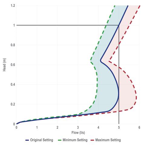
Each hydraulic efficient Hydro-Brake® Optimum has a unique, triple head / discharge curve showing the minimum and maximum flow rate range for that unit.
The initial setting of the designed unit will be the centre line, shown in blue. Post-installation, the unit can be adjusted to any flow rate within the minimum / maximum range.
Use our Online Design Tool (hydro-int.design) to precisely design a Hydro-Brake Optimum to meet your site-specific requirements.
In the tool, there are a number of design objectives to choose from which determine which type of Hydro-Brake® Optimum is best for your site. These are:
Minimise onsite storage - Hydraulic Efficiency design (HE Online Design Tool objective)
This is the default setting in the tool as it the best performance. Matching the Flush-Flo™ point equal to the design point means that the device will pass forward as much flow as possible during the earlier stages of a storm, reducing the amount of water that needs to be stored upstream.
To help engineers be prepared for the effects of urban creep, changes in regulations or changing climate, Hydraulic Efficient S-type units are now supplied with an adjustable inlet as standard. This future-proof feature allows flow adjustments post installation without the need to replace the whole device. A unique triple flow head/discharge curve is generated by the Online Design Tool for these units.
The adjustable inlet can be added to Conical Hydro-Brake® Optimum units as an optional extra by selecting the ‘Future proof (FP)’ option in the Online Design Tool.
Specifying a Flush-Flo™ point (FF objective)
Reducing the Flush-Flo™ point reduces the physical size of the device, so if the exact available space is known then the Flush-Flo™ point may be tuned to give the most hydraulically efficient performance within the space available (CU). Note: this option will disable other objective selections. Custom Flush-Flo™ points can be specified, enabling the design of precise ‘complex flow control’ arrangements where the pre-developed hydrology is aligned to the post-developed site (FF).
Minimise blockage risk (CL Online Design Tool objective)
Reducing the Flush-Flo™ point reduces the size of the device, so if the exact available space is known then the Flush-Flo™ point may be tuned to give the most hydraulically efficient performance within the space available.
Linear discharge profile (CU Online Design Tool objective)
This objective generates a discharge as close to linear as possible, providing similar hydraulic performance to an orifice plate, but with internal clearances approximately two to four times larger. This objective also compacts the unit to its smallest physical size, making it ideal for retrofit into existing chambers.
Other design options
Custom Flush-Flo™ points can be specified, enabling the design of precise ‘complex flow control’ arrangements where the pre-developed hydrology is aligned to the post-developed site.
There are now a variety of industry guidance documents applied at national and regional levels and they are not totally consistent in terms of their stance on minimum flow rates or minimum flow control sizes.
The approaches range from BS8582:2013, which states “controls smaller than 25 mm are possible if protected [from blockage]” up to the advice given by water companies, which can set a minimum acceptable opening size for adoptable flow controls for surface water only systems of >50 mm for protected orifices and >100 mm for unprotected orifices. To find out more about about our low flow solutions call +44 (0)1275 337937 or email stormwater@hydro-int.com.
Using other design software tools
Hydro-Brake® Optimum is available in the hydraulic modelling packages AutoDesk InfoDrainage®, Site3D and Causeway Flow.
To model the new adjustable inlet, engineers should contact Hydro International for the triple head / discharge curve and hydraulic data for manual input.
email: stormwater@hydro-int.com
Design your Hydro-Brake® Optimum
Use our Online Design Tool to precisely engineer a Hydro-Brake® Optimum flow control to meet your specific site requirements.