Your questions answered on the Hydro-Brake Optimum new adjustable inlet feature
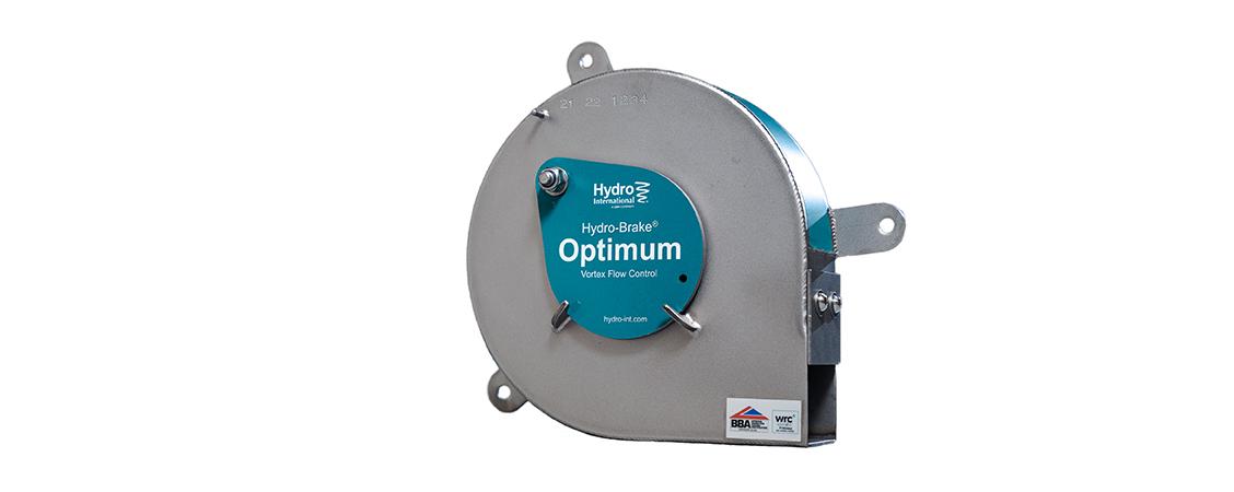
In this blog our Product Manager, Ben Puddy, answers some questions you've been asking about the new adjustable inlet feature on our most popular Hydro-Brake® Optimum vortex flow control.
"Earlier this year, we upgraded our Hydro-Brake® Optimum to include an adjustable inlet feature as standard. Why? Because there is an industry and environmental demand for future-proofing installations, we wanted to provide engineers and designers with the tools they need to stay ahead of the competition.
With climate change, site requirements and the everchanging regulations, we want to support designers and professionals to adapt at the drop of a hat – both for future planning and with retrofitting.
So how does this work, exactly?
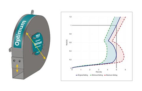
The adjustable inlet allows up to plus or minus 20% change in design flow should it ever be needed. This could be because of urban creep, an additional development upstream, or as a result of climate change. When using the Online Design Tool, the adjustable inlet will be automatically included on units designed with the default ‘Hydraulically Efficient’ objective. The tool will output a unique triple-head curve showing the maximum and minimum flow rate range, meaning the flow rate can be changed to any within the range.
How do I design it?
So, you’ve decided that it’s something you want to go with, how do you navigate the free Online Design Tool? Let’s go through it in a step-by-step guide:
- First things first, you’ll need to register (if you haven’t already) and create an account which you can do via hydro-int.design. Once you’re set up, select Hydro-Brake® Optimum on the homepage.
- Here you’ll need to complete the design inputs section which can be seen on the left side of your screen – this includes details such as site number and reference number (put the postcode of the site if you don’t have a reference number). Add in the required design head and design flow.
Please be aware of the metrics too – this will automatically filter to your location, so good to check! - We then move on to the customisable options for the Hydro-Brake® Optimum, which is where you can select different objectives:
a) Hydraulically Efficient (HE) – this design passes forward as much flow as possible early in a storm event, enabling engineers to reduce the amount of upstream storage volume required. Now with the adjustable inlet as standard.
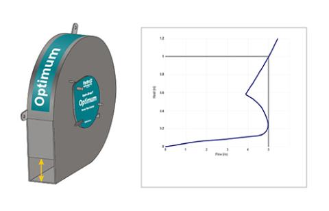
b) Minimise Blockage Risk (CL) – this option makes the inlet and outlet openings as large as possible while still delivering the same design flow.
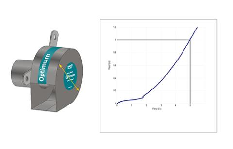
c) Linear Discharge Profile (CU) – this design generates a discharge as close to linear as possible, providing similar hydraulic performance to an orifice plate, but with internal clearances approximately two to four times larger. This design objective also compacts the unit size to the smallest possible.
Note again, that the Online Design Tool will automatically default to HE (Hydraulically Efficient) to give you the best performing unit in terms of storage optimisation and will also include the adjustable inlet.
- Complete the remaining sections as prompted concerning your site and then click ’Design’.
- The Online Design Tool will then produce a design output which will include a unit reference, and hydraulic characteristics showing the discharge rate versus the head and then provide you with the control points, unit dimensions and key installation dimensions.
Hydraulically Efficient units will automatically output a unique triple curve hydraulic characteristics graph. These curves demonstrate the adjustability range of the designed unit. The blue line is the original setting the unit will be supplied as, the dashed green line is the minimum rate, and the dashed red line illustrates the maximum setting and flow.
Why isn't the adjustable inlet on every Hydro-Brake® Optimum?
If you design a “CL” unit, the inlet size is made as large as possible to reduce blockage risk. Adding an adjustable inlet to adjust the flow by reducing the inlet size is therefore counterintuitive meaning the adjustable inlet is not available for the CL objective.
Similarly, a unit designed to the “CU” objective will be as small as possible to produce a linear discharge curve, making the size too small to fit an adjustable inlet.
Do note however, if you need a conical unit without a sump and still would like the adjustable inlet, you can add this manually to your design options.
If you get stuck at any point, there are helpful tips and explanations at each stage of the design process.
You still have the options to save your designs and to output the data and associated drawings and head/discharge curve.
Try out some Hydraulically Efficient designs in our Online Design Tool (hydro-int.design) and take a look at the triple head/discharge curve. If you aren’t already an online design tool user, it’s free to register and use.
Our technical team is also able to advise you on the sizing and design of Hydro-Brake® Optimum flow controls, if you’re not sure what you need. Give them a call on 01275 337937 or drop them an email at stormwater@hydro-int.com."